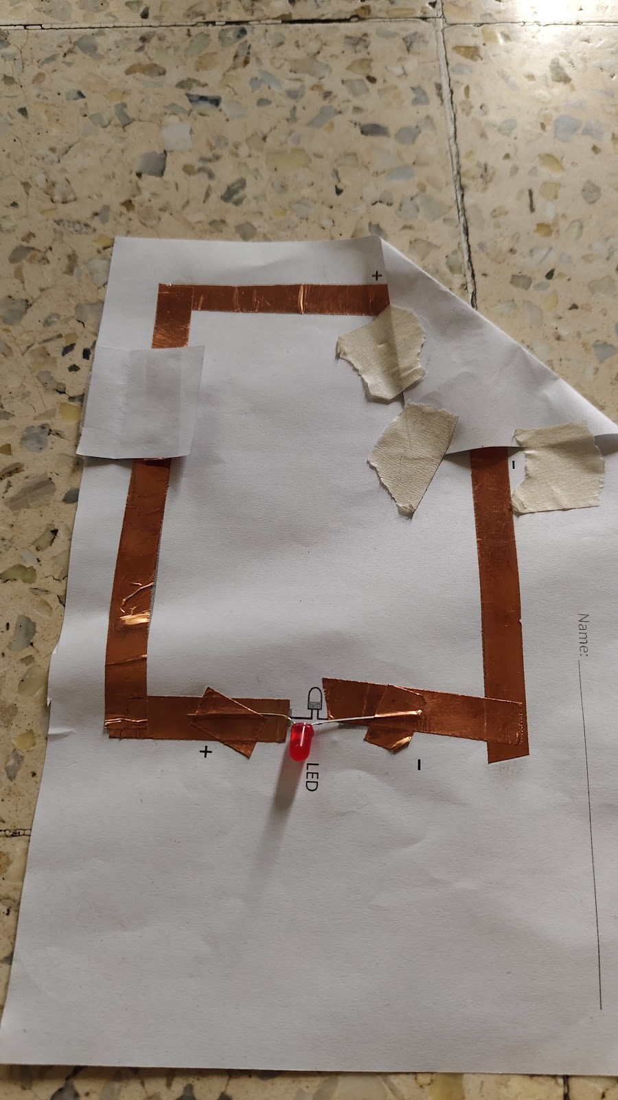
Simple Circuit
Components:
Copper tape
LED
Coin cell battery (3V)
Steps:
Create a rectangle using copper tape.
Attach the LED to the copper tape, ensuring the longer leg (anode) is connected to the positive side and the shorter leg (cathode) to the negative side.
Place the coin cell battery in one corner with the negative side facing down.
Connect the copper tape to both ends of the battery.
Result:
Solution:
Series Circuit
Components:
Copper tape
2 LEDs
Coin cell batteries
Steps:
Connect the copper tape in a rectangle.
Attach 2 LEDs in a row (series) to the copper tape.
Ensure the positive leg of the first LED is connected to the battery's positive side, and the negative leg of the second LED is connected to the battery's negative side.
Result:
Both LEDs glow, but they are dimmer than in the simple circuit. (They glow properly with 2 coin cell batteries.
The voltage is shared between the LEDs (1.5V each for a 3V battery).
The current remains the same (20 mA with a resistor).
Parallel Circuit
Components:
Copper tape
2 LEDs
Coin cell battery
Steps:
Connect the copper tape in a rectangle.
Attach two LEDs side by side (in parallel) to the copper tape.
Ensure both LEDs are connected directly to the battery's positive and negative sides.
Result:
Both LEDs glow brightly.
The voltage across each LED is the same (3V), but the current is split between them.
In the simulation, the current is 38.9 mA, which exceeds the recommended maximum.
Solution:
Breadboard Connections
Description:
The breadboard has two sets of vertical power rails (positive and negative) on the sides.
The main grid is horizontally connected in rows, separated by a central partition.
To connect components:
Example:
Connect the LED's anode (longer leg) to a resistor, then to the positive rail.
Connect the LED's cathode (shorter leg) to the negative rail.
RC Robot
Components:
Copper tape
9V battery
Copper wires
Foam sheet
Printouts
Soldering iron
100 RPM motors
Steps:
Stick the printouts onto the foam sheet to create the robot's body.
Solder wires to the copper tape for electrical connections.
Solder all intersection points on the copper tape to ensure connectivity.
Stick copper tape onto the template to create the circuit.
Connect the motors to the copper tape and power them with the 9V battery.
https://youtube.com/shorts/vFVS9yz7S04?feature=share
Working:
Power Supply:
Remote Control Operation:
The remote control has buttons that correspond to different movements (e.g., forward, left, right).
When a switch is pressed, it completes a specific circuit, sending a signal to the robot.
Motor Activation:
Movement:
Stopping:
LDR, LED, and Transistor Circuit
Description:
This circuit utilises a Light-Dependent Resistor (LDR) to control an LED assisted by a transistor. When light falls on the LDR, its resistance decreases, allowing current to flow through the transistor and turn on the LED.


Working of electric components
LED (Light Emitting Diode):
An LED is a tiny light that glows when electricity passes through it.
It only works when connected the right way (positive to positive, negative to negative).
LDR (Light Dependent Resistor):
An LDR is a special resistor that changes its resistance in response to light.
In bright light, its resistance is low (lets more electricity flow).
In darkness, its resistance is high (lets less electricity flow).
Battery:
Resistor:
colour codes of resistors-
5 band resistor,
- Colour code - Red, Grey, Blue, Red, Brown
- Red = 2, Grey = 8, Blue = 6
Multiplier [Brown colour band] = 100 Ohms
Calculation-
Multiplier for Brown colour = 100 Ohms
286×100=28600 Ohm
100028600=28.6 kOhm (Convert into kilo-ohm)
Tolerance =1%
1% tolerance of 28.6 kOhm = 0.286
28.6 +1% = 28.886 kOhm
28.6 - 1%=28.314 kOhm
Solar panel circuit for solar desk lamp
Circuit Designed in Tinker CAD -
Circuit connections -
The following components are required for making the above circuit:
Connections:
The positive terminal of the battery and the positive terminal of the solar panel are connected to the common terminal of the 2-way switch.
Terminal two of the switch is connected to the anode of the LED.
The anode of the LED is connected to the resistor, the first terminal of the LDR, and the base of the transistor.
The negative terminal of the battery is connected to the negative terminal of the solar panel, which is further connected to the diode, the second terminal of the LDR, and the emitter of the transistor.
The cathode of the resistor is connected to the collector of the transistor.
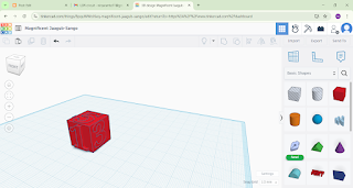
3D Designing:
3D designing involves creating a digital model of the circuit enclosure or any other component using CAD (Computer-Aided Design) software.
The design can be optimised for 3D printing by ensuring proper wall thickness, minimal overhangs, and support structures where necessary. The model should be exported in a compatible file format for 3D printing.


3D Printing:
Model: Flash Forge Adventurer Pro
Materials: PLA, ABS
Nozzle Temperature for PLA: 210°C
Bed Temperature for PLA: 50°C
Nozzle Temperature for ABS: 230–250°C
Bed Temperature for ABS: 90–110°C
orca slicer
Orca Slicer is a slicing software that converts 3D models (in formats such as STL, OBJ, or 3MF) into G-code, the language understood by 3D printers. The G-code contains instructions for the printer, such as where to move the print head, how fast to extrude filament, and when to turn fans on or off
using Orca Slicer-
1. Importing the 3D Model
2. Model Preparation
Scale: Adjust the model's size to suit your needs.
Rotate: Change the orientation of the model to optimise print quality or reduce supports.
Cut: Split large models into smaller, printable parts.
3. Slicing the Model
After configuring the settings, Orca Slicer processes the 3D model and divides it into layers. Each layer is represented as a set of instructions that the printer follows to create the object.
The software uses advanced algorithms to:
Optimise toolpaths for efficiency and quality.
Generate support structures where needed.
Calculate filament extrusion rates and retraction settings to prevent stringing.
4. Exporting G-code
Once the slicing process is complete, Orca Slicer exports the G-code file. This file contains all the instructions the printer needs to create the physical object.
The G-code can be saved to an SD card, USB drive, or sent directly to the printer via a connected computer or network.
Circuit with a 9-volt battery (Ohm's law)
1. Tinker CAD simulation
I used 2 resistors, resistor#1 is 220 Ω, resistor#2 is 110 Ω
The current is 21.8mA, and the voltage is 6.88 volts.
Theoretical calculation Voltage is denoted by v
Ampere (current) is denoted by I
Resistance is denoted by R
Ohm's law states that V = IR; therefore, V / I = R
I (Simulated)= 21.8 mA = 0.0218 A, V (Simulated) across resistors = 6.88 V
6.88/0.0218 = R
R = 315.6 Ω
Practical results
Current (Measured) = 21.8 mA =0.0218 A
Voltage (Measured) = 6.89 V
Ohm's law states that V = IR; therefore, V / I = R,
R= 6.89/0.0218 =
Resistance = 316 Ω
Animation using PictoBlox 1.
I created a game using PictoBlox, featuring two sprites (characters): one is a fish and the other is an octopus. The game is that the octopus tries to catch the fish, but I was unable to program the fish to move away from the octopus. Therefore, I set a score after reaching 5 points, the game ends, and the fish turns green. The octopus can be controlled using the arrow keys......
..

Fish programs Switching costumes to fish means that the fish will turn red for the next game after turning green in the last game
glide 1 sec to random positions is there so that the fish keeps gliding forever.
If touching me (octopus), then the score will change by 1 forever
If score = 5, then the fish turns green ( switch costume to Fish-a), the score goes back to zero, and the game ends
When the left arrow key is pressed, the octopus moves on the x-axis by -10 units.
If the up arrow key is pressed, the octopus moves on the y-axis by 10 units.
When the right arrow key is pressed, the octopus moves on the x-axis by 10 units.
If the down arrow key is pressed, then the octopus moves on the y-axis by -10 units.
https://youtu.be/nisaKHXiBRo
2.
I made a second game in which I used two sprites, one of which is a flying cat and the other is a building. Flying Cat Programs When the space key is pressed, the game starts, and the building begins to move backwards; as a result, the cat appears to be flying forward. Each time the cat jumps over a building, the score increases by 1. If the score reaches 5, the cat says 'you won,' and if the cat touches the building, the game is over. If the up arrow key is pressed, then the cat jumps and waits for 0.5 seconds in the air, and then glides back down.
When the space key is pressed, the building gets set on 300 on the x-axis, and the building keeps changing its position by -10 on the x-axis forever.
https://youtu.be/u7UBS5WVzQc
Temperature and humidity monitor
components
Arduino uno
DHT 11 (Digital humidity and temperature)
jumper wires
bread board
Arduino cable
connections
vcc - 5v
gnd - gnd
data - digital pin 2
The code shows temperature and humidity on the computer. I uploaded this code to Arduino using Arduino IDE.
https://youtu.be/Dqso5rtR-so
Temperature and humidity monitor
components
Arduino uno
DHT11(Digital humidity and temperature)
jumper wires
breadboard
Arduino cable
LCD (Liquid crystal display)
This code is similar to the code above; the difference is that the readings will be shown on the LCD
readings
LDR robot
components
LDR(light-dependent resistor)
Transistor
copper tape
wires
60Rpm motors
wheels
The image above shows where to add components. Copper tape will be placed over the grey line that can be seen. The LDR is attached to both ends of this paper circuit; on the other side, the positive terminal of the battery will be connected to the bottom-most line. One terminal of each motor will be connected to the centre, and the other will be connected to the L shape that can be seen near the transistor. The negative terminal of the battery will be connected to the first terminal of the switch. The Wire from the second terminal of the switch is connected to the centre. The body of the robot is PLA material
....

robot's body design
Tinker Cad circuit simulation
3d printed phone stand
I designed this phone stand in Tinkercad. This phone stand is made using PLA material
.....

Project 1. Automatic street light using LDR
components
Battery
LED
Wires
LDR module
Breadboard
Buzzer
connections
The battery's positive is connected to the first column on the breadboard, and the negative is on the second column. LED's positive is connected to the first column, and its negative is connected to row 20 of the breadboard. Buzzer's positive is also connected to the first column, and the negative is connected to row 20. The LDR module's VCC is connected to the first column, GND is connected to the second column, and DO(analogue output pin) is connected to row 20 of the breadboard.
connections
project2.Rainwater alarm
components
rain sensor module
buzzer
LED
battery
bread board
wires
connections
The battery's positive is connected to the first column on the breadboard, and the negative is connected to the second column. LED's positive is connected to the first column, and its negative is connected to row 20 of the breadboard. Buzzer's positive is also connected to the first column, and the negative is connected to row 20. The Rain sensor module VCC is connected to the first column, GND is connected to the second column, and DO is connected to row 20 of the breadboard
project3.Obstacle detection
components
IR sensor
buzzer
LED
battery
breadboard
wires
connections
The battery's positive is connected to the first column on the breadboard, and the negative is connected to the second column. LED's positive is connected to the first column, and its negative is connected to row 20 of the breadboard. Buzzer's positive is also connected to the first column, and the negative is connected to row 20. The IR sensor module VCC is connected to the first column, GND is connected to the second column, and DO is connected to row 20 of the breadboard
Project.4: Automatic plant watering alarm
components
Soil moisture sensor module
Buzzer
LED
Wires
Breadboard
Battery
connections
The battery's positive terminal is connected to the first column, and the negative terminal is connected to the second column. The positive of the buzzer is connected to the first column, and the negative of the buzzer is connected to row 20 of the breadboard positive of the LED is connected to the first column, and the negative is connected to row 20 of the breadboard. The soil sensor module's VCC is connected to the first column, and GND to the second, and DO is connected to row 20 of the breadboard.

composter
components
part 1. composter
faulty geyser
screws and nuts
m-seal
acrylic sheet
tin sheets
3D printed latch
3D printed hinge
3D printed handle
part2. composter stand
oil paint
wood polish
PVC pipes
wooden planks
wheels
screws and nuts
m-seal
Building Process part 1: composter
We started by making holes in the geyser for airflow. We had made a door in the geyser (for adding dry matter) by cutting a rectangular-shaped piece from the geyser and adding hinges and a latch, but because of the door, the geyser was not rotating smoothly, so we had to remove the door. And we added metal sheets to close it up. Then we decided to add the dry material or waste, and remove the compost from the front door itself. For the front door, we used an acrylic sheet, added hinges, and a latch. We attached the handle to the bottom of the geyser with a screw, but because it was loose, we added an m-seal to fix it.
Building Process part 2: composter stand
We connected 4 wooden planks in a hashtag shape using nails. Then we used PVC pipes to make two crosses, and we connected them using screws. Then we placed a rod on the crosses. Later, we used 4 PVC pipes using couplers to make two V shapes and connected them to the rod. We attached 4 wheels to the pipes. On which the composter will be placed, we added stoppers on the pipes so that the composter does not get displaced.
working
- Add a culture packet, which is a combination of beneficial bacteria and fungi
- Introduce kitchen waste
- Rotate 5 times clockwise and 5 times anticlockwise
dog-shaped lamp
components
mdf (medium-density fiberboard)
black and white spray paint
screws and nuts
LED
wires
aluminum foil
jack
9-volt adapter
100 ohm resistor
Fevi bond and hot glue
steps
1. I started by laser cutting these parts:
2. Spray painting the body and the face black, and the legs and ears white.
3. Putting aluminium foil inside the head of the dog and the LED is on the back of its head, like this
4. Assemble the dog and connect it to the jack. This lamp works on a 9V adapter
wooden phone stand
components
wood
wood polish
saw
files and sand paper sandpaper
laser cutter for engraving
steps
1. Cutting the wood into these shapes using a saw and making holes for the charger and the T to fit in using a drill and files
2. engraving design using a laser cutter and polishing.
Bluetooth control robot
components
Arduino Uno (microcontroller)
side switch
lithium-ion battery
lithium-ion battery holder
buzzer
toy motors (60/100 RPM)
wheels
caster wheel
male-female and male-male jumper wires
wires
nuts and bolts
motor driver
Bluetooth module
chassis
double-sided tape
connections
Rather than using 4 motors, I have used only 2. First motor's positive and negative are connected to the motor drivers ' output 1 and 2, respectively, and for the second motor, positive and negative are connected to the motor drivers ' output 3 and 4, respectively. The rest is the same as shown in the above circuit diagram, except the LED, and I have connected the buzzers' positive to Arduino digital pin 6 and negative to GND
control and working
This robot can be controlled by connecting the Bluetooth module to your smartphone through the Arduino Bluetooth control app and going to the car controller. This robot can move front, back, left and right
code
this is the code i used
// ---------- Pin Definitions ----------
#define LED_PIN 13 // Headlight LED
#define BUZZER_PIN 6 // Buzzer (Horn)
#define IN1 12 // Motor A
#define IN2 11
#define IN3 10 // Motor B
#define IN4 9
void setup() {
Serial.begin(9600);
pinMode(LED_PIN, OUTPUT);
pinMode(BUZZER_PIN, OUTPUT);
pinMode(IN1, OUTPUT);
pinMode(IN2, OUTPUT);
pinMode(IN3, OUTPUT);
pinMode(IN4, OUTPUT);
digitalWrite(LED_PIN, LOW);
digitalWrite(BUZZER_PIN, LOW);
}
// ---------- Main Loop ----------
void loop() {
if (Serial.available() > 0) {
char inputvalue = Serial.read();
// -------- Movement Controls --------
if (inputvalue == 'F') { // Forward
digitalWrite(IN1, HIGH);
digitalWrite(IN2, LOW);
digitalWrite(IN3, HIGH);
digitalWrite(IN4, LOW);
}
else if (inputvalue == 'B') { // Backward
digitalWrite(IN1, LOW);
digitalWrite(IN2, HIGH);
digitalWrite(IN3, LOW);
digitalWrite(IN4, HIGH);
}
else if (inputvalue == 'L') { // Left
digitalWrite(IN1, HIGH);
digitalWrite(IN2, LOW);
digitalWrite(IN3, LOW);
digitalWrite(IN4, LOW);
}
else if (inputvalue == 'R') { // Right
digitalWrite(IN1, LOW);
digitalWrite(IN2, LOW);
digitalWrite(IN3, HIGH);
digitalWrite(IN4, LOW);
}
else if (inputvalue == 'S') { // Stop
digitalWrite(IN1, LOW);
digitalWrite(IN2, LOW);
digitalWrite(IN3, LOW);
digitalWrite(IN4, LOW);
}
// -------- LED Controls --------
else if (inputvalue == 'X') { // LED ON
digitalWrite(LED_PIN, HIGH);
}
else if (inputvalue == 'x') { // LED OFF
digitalWrite(LED_PIN, LOW);
}
// -------- Buzzer Controls --------
else if (inputvalue == 'Y') { // Horn ON
digitalWrite(BUZZER_PIN, HIGH);
delay(1000);
digitalWrite(BUZZER_PIN, LOW);
}
}
//delay(1000);
}


.jpg)
.jpg)


.jpg)
.jpg)


.jpg)


